| V&M
Systems |
| P.O. Box 87-56, |
| TAIPEI, TAIWAN |
| T:+8862-8809-8037 |
|
F:+8862-8809-8036 |
| vmc@vmc.com.tw |
|
|
|
|
|
 |
Pipe Network Fluid Flow
Analysis Systems |
|
|
|
|
PipeNet Standard
| is
a powerful tool in the design of single phase steady flow of fluids in pipes. It provides
a quick and cost-effective means of designing real life problems. |
|
|
|
PipeNet Transient
| provides
a speedy and cost-effective means of in-house rigorous transient analysis. The Transient
Module can be used for predicting pressure surges, calculating hydraulic transient forces
or even modelling control systems in flow networks |
|
|
|
PipeNet
Spray/Sprinkler
| is
a powerful tool in the design of fixed fire-protection systems complying with NFPA and FOC
rules. It can be used to design deluge, ringmain, sprinkler and foam solution systems for
offshore platforms, refineries, petrochemical and chemical plants |
|
|
|
 |
|
|
|
PipeNet Standard |
|
| Networks |
| Networks can be defined from a wide choice of elements-pipes,
ducts, nozzles, pumps/fans, filters, non-return valves, control valves, leaks, fixed
pressure drops, orifice plates, properties and specifications. |
| PIPENET has built-in data of fittings (Crane), gases, steam (IFC67
standard) and pipe schedules (ANSI, JIN and DIN). Users can also create their own pump,
pipe schedule, control valve, fittings and fluids data libraries that can be used in any
network. |
| PIPENET allows the properties of the fluid to be constant or to
vary in the network system. |
|
|
| Fittings |
| Multiple fittings can be inserted on a pipe and it is not necessary
to treat them as separate entities. They are simply defined as attributes of a pipe. This
is a powerful feature of PIPENET. |
|
|
| Schematic
Capabilities and On-line Help |
| A network can be defined using schematic or text input. However, a
text input network can also be displayed using the schematic. Results can also be
displayed on the schematic. Online help is also available for more information on the
features of PIPENET. |
|
|
| Pipe
Sizing and Blocked and Broken Pipes |
| PIPENET has very powerful pipe sizing capabilities. It Can select
standard nominal bores from user-defined or built-in pipe schedule data. A blocked or
broken pipe can also be modelled in network. |
|
|
| Cavitation |
| The
program will detect and report the likely occurrence of both deaeration and vaporisation
cavitation. |
| Orifice
Plates |
| Restriction
Orifice plates can be modelled in compliance with Crane, Heriot-watt and
BS 1042, taking
into account downstream pressure recovery. Given the pressure drop the orifice diameter is
determined, and vice-versa. |
| Modelling
of Gases and Low-Pressure Gases |
| These
can be modelled using standard pressure loss correlations and correction factors,
making the module suitable for the design of gas distribution systems. |
| Filters |
| A
filter is available for use where accurate modelling is required. On the other hand,
filters can simply be modelled as fittings |
| Leaks |
| This
is a powerful feature of the program and is particularly useful for flow analysis of
ventilation systems where the handing of leaks is very important. Leaks are modelled in
accordance with the requirements of BS5588. Leaks may be defined as between two nodes of a
network (for instance to represent a leak around a door between rooms) or to the
atmosphere. |
| Control
Valves |
| This
regulates flow or pressure in a network. The valve setting can be specified by the user or
based on a sensor - pressure at a node, flow in a pipe or pressure difference between two
nodes. |
|
Hydraulic Gradient Capability |
| Hydraulic gradient capability calculations can be
performed for incompressible fluids. |
| Nozzles
can be Modelled using Fundamental Equations of Flow |
| Ambient
Pressure Correction |
| Particularly used in ventilation system calculations involving tall
chimney stacks, automatic correction for the variation in ambient pressure with height is
available. |
| Output |
| Output
reports can be created using Word, Write or PIPENET Output Browser. |
| Pump/Fan |
| A
standard PIPENET pre-processor is provided for the creation of libraries of performance
characteristics. These can be readily accessed to include pumps/fans in networks. A given
pump type need therefore be input to the module only once for it to be available for
repeated use in different network designs. Pumps, including booster pumps, can be
connected in series or parallel at any point in the network. |
|
|
 |
|
[Top to this page] |
|
|
|
PipeNet
Transient |
|
| Built-in
Element Models |
| The
following range of element models is available at present |
|
í |
Pipes |
|
í |
Pumps:Simple
pump, Turbo pump |
|
í |
| Valves: |
Operating valve, non-return valve, check valve, fluid damped check valve,
liquid surge relief valve, regulator valve, inertial check valve. |
|
|
í |
Tanks:Accumulator
tank, simple tank, surge tank |
|
í |
Vacuum
breaker / Air release valve |
|
í |
Caissons |
|
í |
Control
Systems: Pressure of Flow sensor, PID controller, Transfer function |
|
| New
models can be developed if required. |
| Fittings |
| Multiple
fittings can be inserted on a pipe and it is not necessary to treat them as separate
entities. They are simply defined as attributes of a pipe. This is a powerful feature of
PIPENET. |
| Time
Operation of Valves |
| The
operating valve model can be used to represent a manual valve or a control valve. In the
case of a manual valve, its operation would be directly specified by a user-defined
boundary condition. In the case of a control valve, the operation would be defined by a
signal from the control loop. |
| Operation
of Pumps (Simple or Turbo) |
| The
pressure increase provided by a simple pump depends on its speed and performance curve.
The performance curve can be entered and saved as library. The pump speed is specified
directly or by a signal from the control loop. The turbo pump can additionally handle the
'spin down' due to pump failure. |
| Control
Systems |
| Control
systems allow components such as pumps or valves to react to changes in pressure or
flowrate in some part of the network. |
| A
sensor measures an instantaneous reading for pressure or flowrate, which is converted to a
signal for the controlled device by means of a PID controller. Transfer functions can also
be included in the control loop to model the dynamics of the sensor and the controlled
device. |
| Hydraulic
Transient Forces |
| Pipework
can experience significant stresses and movements, or even sustain damage, due to fluid
transient phenomena such as water hammer. PIPENET can calculate hydraulic transient forces
and these can be read by pipe stress or structural analysis programs for further
processing. |
| Initial
Conditions |
| PIPENET
can automatically generate the initial steady state solution. For cases where the starting
point is not steady state, the user can supply own starting condition. |
| Stationary
Initial Condition |
| Often a pipe network system would start from a stationary condition where the
flow is zero throughout the system. It is possible to do this automatically. |
| Vapour
Cavitation Modelling |
| Under transient flow conditions pipework can locally experience very low
pressures. Generally these would be cyclic in nature. Constant formation and collapse of
vapour cavities would accompany this phenomenon in cycles. PIPENET can model this. |
| Automatic
Calculation of Wave Speed and Time Step |
| Under transient flow conditions, the effect of a disturbance makes itself felt
throughout the system in the form of waves. The wave speed depends on parameters such as
the modulus of elasticity of the pipe material, diameter, wall thickness, the Poisson's
ratio and the compressibility of the fluid. The wave speed is of fundamental importance,
and PIPENET can calculate it automatically. The program can also determine the time step
for calculation automatically. The user can optionally specify both the wave speed and the
time step. |
| Tabular
Output |
| Typically, a large amount of calculated results would be produced by transient
analysis. For this reason, the Transient module allows the user to define which variables
are to be output and in what format. |
| Graphical
Output |
| While tabular output is useful for a thorough analysis, graphical output can be
used to get a quick overview. The Transient module allows the user to output selected
variables graphically. The graphs can also be viewed as movies in real time. |
| Forces
Output |
| The
force-time history can be output in the form of a forces file. This file is specifically
intended for further processing by pipe stress or structural analysis program. |
| Functions
available for Boundary Conditions |
| The
following functions may be used for specifying the boundary conditions. (These are time
dependent.) |
|
í |
Constant |
í |
Power Ramp |
|
í |
Sine Wave |
í |
Exponential |
|
í |
Damped Sine Wave |
í |
Asymmetric Pulse |
|
í |
Profile -
linear, step or cubic |
|
|
|
|
|
 |
|
[Top to this page] |
|
|
|
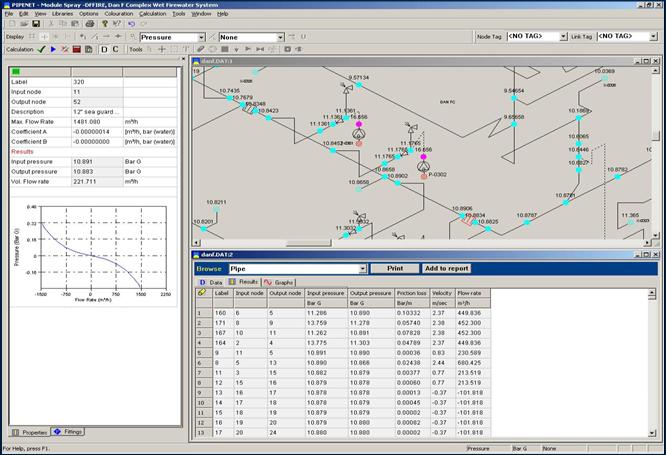
PipeNet Spray/Sprinkler |
|
| Network |
| Networks
can be defined from a wide choice of elements - pipes and fittings, nozzles, deluge
valves, pumps/fans, filters, non-return valves, orifice plates, special equipment items,
specifications and overboard dump valves. |
| PipeNet has built-in data of fittings, pipe
linings and pipe schedules. Users can also create their own pump, pipe schedule, pipe
lining, nozzle and deluge valve data libraries that can be used in any network. |
| Fittings |
| Multiple
fittings can be inserted on a pipe and it is not necessary to treat them as separate
entities. They are simply defined as attributes of a pipe. This is a powerful feature of
PipeNet. |
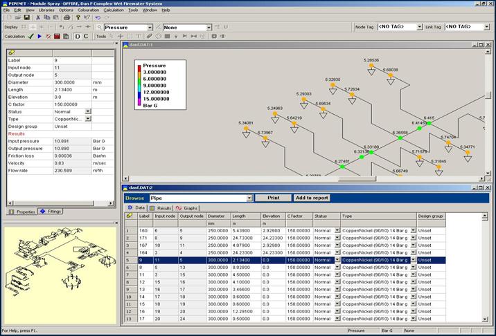
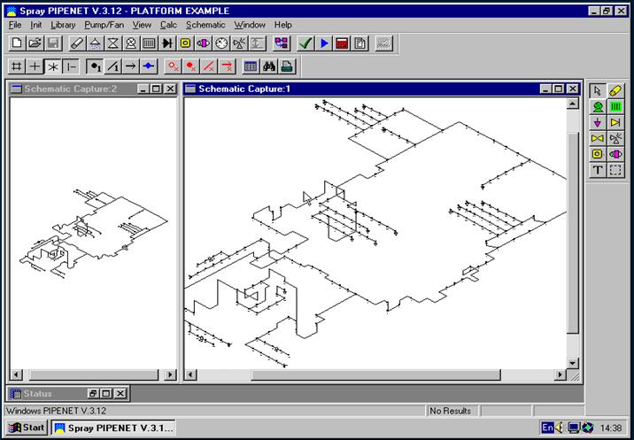
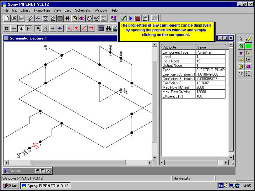
| Schematic
Capabilities and On-line Help |
| A
network can be defined using schematic or text input. However, a text input network can
also be displayed using the schematic. Results can also be displayed on the schematic.
On-line help is also available for more information on the features of PipeNet. |
| Ringmain
Capabilities |
| Fire
pumps (including booster pumps) may be connected in series or in parallel anywhere in the
network. One or more of them may be operating in given scenario, and it is easy to switch
pumps on and off. For ringmain systems, the program handles the following tasks: |
|
í |
pump selection
calculations using manufacturer's pump data |
|
í |
connecting pumps
or booster pumps in series or in parallel at any point in the network |
|
í |
modelling of
conventional deluge valves in addition to constant flow deluge valves |
|
í |
attachment of
monitors and hydrants |
|
í |
performing case
studies with different fire scenarios |
|
í |
use of lined and
unlined pipes in the same system |
|
í |
modelling
operation of isolation valves |
|
í |
connecting
loops, grids and trees in any combination |
|
í |
modelling of
breaks and blocks in pipework |
|
| Deluge
Valves |
Deluge valves may be of conventional "clack" shut type or
"constant flow" type.
Monitors and hydrants may be attached anywhere in the network. Loops, grids and trees may
be incorporated in any combination. Lined and unlined pipes can be used in the same
system. Pump selection calculations can be performed or manufacturer's data can be used to
model the exact behaviour of the system once a pump has been selected. The module makes it
possible to perform cases studies with different fire scenarios. Breaks and blocks in the
pipework may be modelled with ease. |
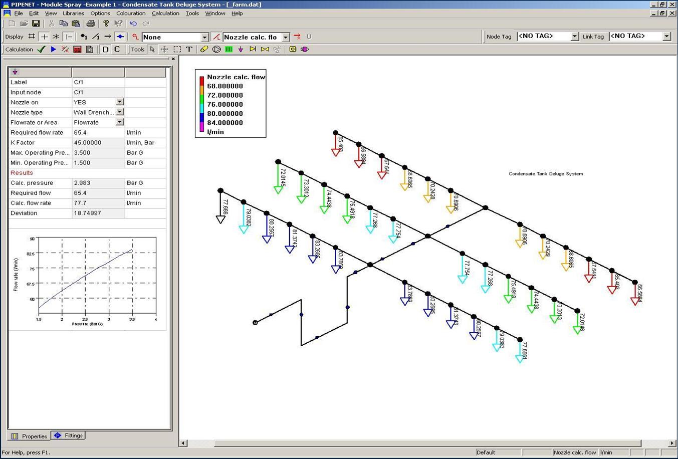
| Deluge
System Capabilities |
| A
powerful range of alternative calculation types is available. The Program can
automatically identify the most remote nozzle and set its flow rate or the average density
option may be chosen. The user may even specify the flow rate or flow density at a
selected nozzle, or the available inlet pressure or flow rate. Orifice plates may be sized
to balance the pressure required by the deluge system and the pressure available in the
ringmain. For deluge systems the program can handle. |
|
í |
automatic
identification of the most remote nozzle and setting its flow rate |
|
í |
sizing orifice
plates to match the pressure required by the deluge system |
|
í |
specifying the
flow rate or the flow density at a specific nozzle |
|
í |
specifying the
available inlet pressure |
|
í |
selecting the
average density option |
|
| Pipe
Schedule |
| Pipes
may be lined or unlined, selected from eight built-in pipe schedules and three pipe
linings. Alternatively, users can set up their own pipe schedule and lining data. Pipe
sizes can be referred to by nominal or external diameters. A network can include several
different lined and unlined pipe types. |
| Pipe
Sizing |
| The
user may leave some or all pipe sizes unspecified. PIPENET will automatically suggest
appropriate pipe sizes based on the user selected pipe schedule |
| Orifice
Plates |
| Restriction
Orifice plates can be modelled in compliance with Crane, Heriot-watt and BS1042, taking
into account downstream pressure recovery. Given the pressure drop the orifice diameter is
determined, and vice-versa. |
| Remote
Nozzle Calculation |
| Calculations
can match the minimum flow rate required at the nozzle that is hydraulically most remote.
Nozzles may also be switched on or off individually or in banks. |
| Materials
Take-Off |
| Materials
take-off tables can also be produced for weight and cost estimation purposes. |
| Output |
| Output
reports can be created using Word, Write or PIPENET Output Browser. |
| Pump/Fan |
| A
standard PIPENET pre-processor is provided for the creation of libraries of performance
characteristics. These can be readily accessed to include pumps, fans etc. in networks. A
given pump type need therefore be input to the module only once for it to be available for
repeated use in different network designs. |
|
|
 |
 |
|
 |
|
 |
|
[Top to this page] |
|
